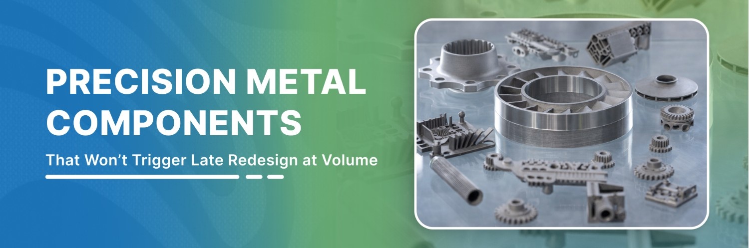
“Precision components” become expensive when it’s treated as a label instead of acceptance criteria.
At production volume, the failure mode is predictable: critical features drift, inspection load grows, secondary ops creep in, and suppliers hold performance until the first change or schedule squeeze.
This guide gives you a decision framework to prevent that. You will define precision in verifiable terms, screen manufacturing methods by fit, apply a PM decision gate where it belongs, plan the material + finishing stack by failure mode, and vet suppliers by control discipline.
Key Takeaways
Define “precision components” using critical-to-function features and a verification plan, not generic claims.
Screen manufacturing methods by volume, geometry, material family, and secondary requirements before vendor shortlisting.
Use a PM decision gate: confirm PM fit and print feasibility before tooling spend.
Build a performance stack: material family plus secondary operations aligned to the failure mode.
Select suppliers based on tooling governance, control plans, measurement discipline, and traceability.
Define “Precision Components” as Acceptance Criteria You Can Quote and Verify
“Precision” only helps you if it changes behavior. It should change what you put on the drawing, what you ask for in the RFQ, and what gets verified before parts hit an assembly line.
Start by separating critical-to-function characteristics from everything else. These control the assembly's success:
Alignment & Fit: Bearing seats, alignment bores, and datum schemes.
Interfaces: Gear tooth profiles, mating geometry, and stack-up features.
Sealing & Load: Sealing faces and high-stress load transfer points.
Translate “Precision” into Acceptance Language
If you cannot classify a requirement into one of these three buckets, you have created ambiguity that will eventually surface as rework or supplier disputes:
What Must Hold: Features that cannot drift without breaking function.
What Can Vary: Non-critical dimensions where a wider band does not change performance.
Cosmetic vs. Functional: Is that surface finish for "looks," or does it affect assembly yield?
Lock the Verification Plan
Precision is proven by how it is measured and how often it is checked.
Specify the gage method for critical features (the method matters as much as the number).
Set a sampling cadence that matches risk and volume.
Define the containment trigger: What happens when a part is out of spec? Who stops the line, and how is the batch quarantined?
Define the Change Boundary
Most precision failures happen after an unannounced change. Call out exactly what requires explicit re-approval:
Material grade substitutions.
Tooling modifications or refurbishments.
Shifts in measurement methods or locations.
With “precision” defined this way, method selection becomes straightforward: you can choose the manufacturing route that can hold the critical features and verification plan without forcing expensive cleanup.
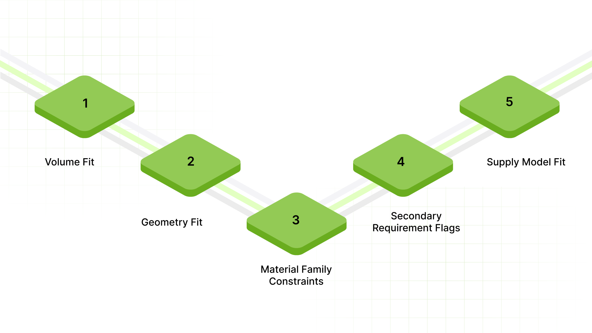
Choose Manufacturing Methods Using Fit Filters
A precision-components program usually goes off track when method selection is treated as a downstream detail. At the production scale, the manufacturing route determines inspection load, yield stability, lead-time risk, and how often you will be forced into secondary cleanup.
Use these five fit filters to pick the correct lane early:
Volume Fit
Prototype economics reward flexibility. Production economics reward repeatability. Once you move into sustained demand, the method must hold a stable output without constant human intervention.
Ask a simple question: Will this part be made as a one-time run, periodic batches, or a continuous replenishment item? Method choice changes as soon as the answer shifts from “occasional” to “repeat.”
Geometry Fit
Precision failure often starts with geometry that is technically possible, but operationally expensive. Features that typically trigger mismatch include complex internal forms, multi-level transitions, and non-round internal geometry.
These features tend to amplify cycle time, tool wear, and inspection complexity when forced into the wrong method lane.
Material Family Constraints
Do not evaluate “precision components” as if every metal behaves the same. Some routes have strong coverage in certain alloys and weaker coverage in others, especially when corrosion resistance, magnetic behavior, or wear performance is non-negotiable.
At this stage, you are confirming that the method lane can reliably run the material family you need.
Secondary Requirement Flags
Secondary operations are a consequence of the spec. If heat treatment, plating/coatings, tight post-processing, or specific surface conditions are inherent to performance, that changes which methods remain viable and how you should frame the RFQ.
You are identifying whether they are unavoidable and therefore must be planned.
Supply Model Fit
A batch-buy model tolerates longer lead times and larger inventories. A Kanban/JIT model does not. If your line depends on predictable replenishment, the method must support stable cadence and repeatable output across time.
Once you narrow the method lane using these filters, a quick side-by-side view prevents “defaulting to machining” out of habit.
Process Fit for Precision Components at Volume
Use the table to decide what you are buying: flexibility, repeatability, or net-shape consolidation.
Attribute | CNC machining | Powder metallurgy (net/near-net) | Die casting | MIM | Stamping/forging |
|---|---|---|---|---|---|
Best-fit volume band | Prototype to medium volumes; also, selective high-volume for simple parts | Medium to high volumes with stable demand | High volume where alloy and geometry suit | High volume, smaller parts | High volume for suitable geometries |
Geometry fit (internal features) | Strong external geometry; internal complexity often drives cost/time | Strong for complex net-shape features and repeatable forms | Strong for complex shapes; internal features depend on design | Very strong for small complex geometry | Limited internal complexity; strong for certain strength needs |
Tooling commitment | Low to moderate | Higher upfront | Higher upfront | Higher upfront | Higher upfront |
Secondary ops reliance | Moderate (finishing common) | Planned, targeted (not blanket) | Moderate (machining common on critical faces) | Moderate | Moderate |
Waste profile | Higher (subtractive) | Lower material loss | Moderate | Low | Lower than machining |
Risk drivers | Cycle time, tool wear on complex features, and cost volatility | Fit to part envelope and spec stack, upfront tooling planning | Tooling lead time, porosity/finish constraints | Size limits, debinding/sinter control | Die life, design constraints |
Best use case | Fast iteration, complex external forms, low tooling appetite | Cost-effective repeat production with consolidated features | High-volume housings and complex shapes where the alloy fit is correct | Small, intricate components where traditional routes are inefficient | High-volume parts with geometry suited to forming |
Note: This table is a screening tool. The “best” method is the one that minimizes lifecycle friction for your acceptance criteria at your required cadence.
After the method lane is clear, treat powder metallurgy as a gated decision. Validate fit and print feasibility before any tooling commitment.
Powder Metallurgy Decision Gate
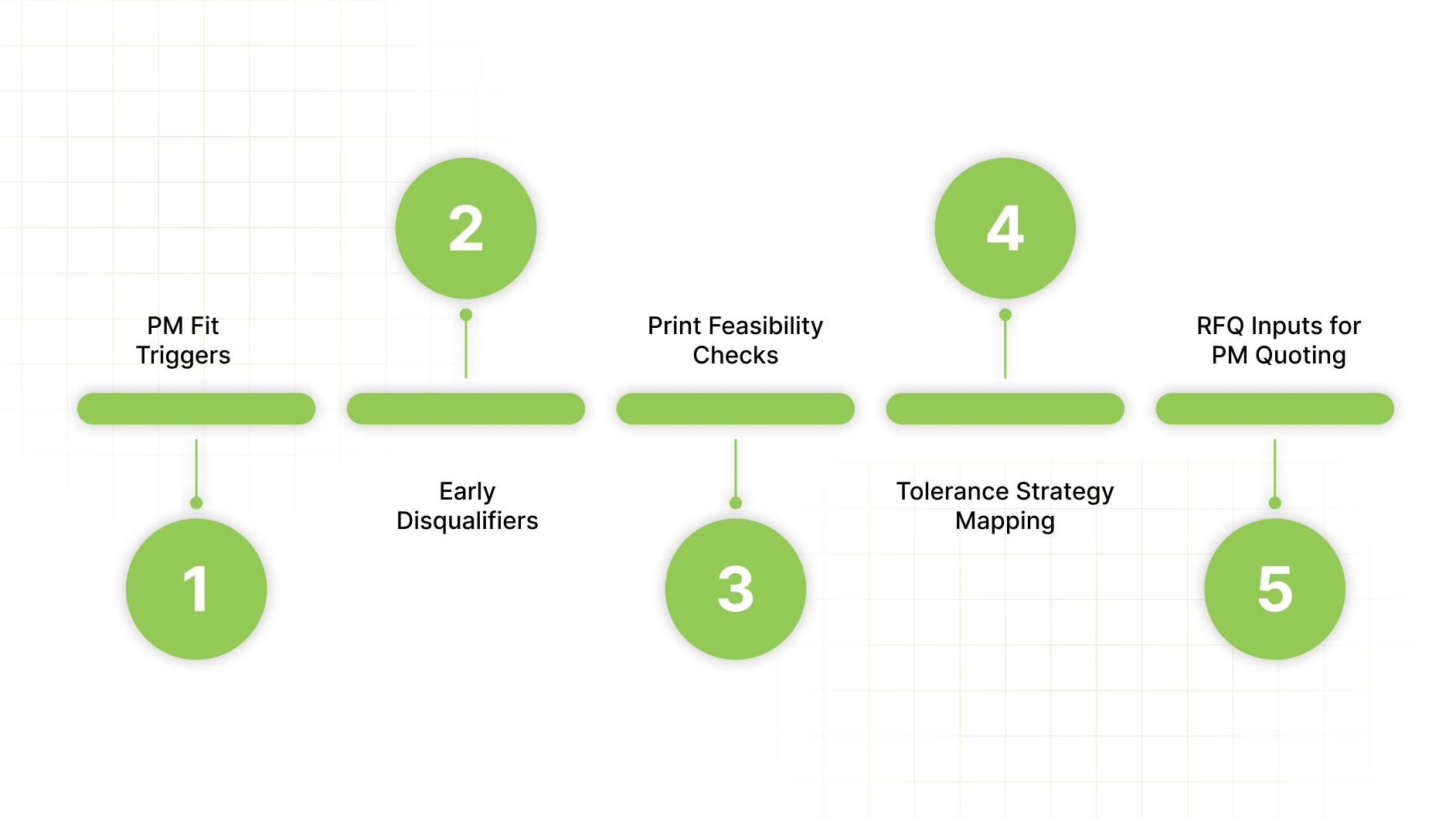
Once PM is in the viable lane, the only smart move is to gate it before tooling, fit first, print feasibility second. The goal is simple: confirm the part is a strong PM candidate and confirm the print will not force late redesign after tooling starts.
PM Fit Triggers
PM is usually worth serious consideration when the program has at least one of these characteristics:
Net/near-net value is real. The part has enough material removal, complex features, or machining touchpoints today that a net-shape route could remove steps rather than just shift them.
Repeatability at volume matters more than one-off perfection. You need stable output across runs with predictable verification and low variation drift.
Internal geometry drives cost or risk in other routes. The part has features that create cycle-time drag, tool wear, or inspection burden when produced by other methods.
This is a fit check tied to program economics and control requirements.
What Does that Look Like in the Real World?
Let's look at this Sterling Sintered case study: lock hardware
A lock-hardware program is a clean example of where those triggers show up at the same time. The starting point was a multi-part build: two stampings, two cold-headed pins, and one powder-metal component, plus the coordination and assembly work that comes with it.
Sterling’s early engineering involvement consolidated that stack into a single complex powder-metal part that ships with no sub-assembly required. The performance requirement was not academic.
The assembly had to withstand a high-impact torque test using a three-foot black iron pipe and a 16-pound sledgehammer, and the part exceeded the customer’s test requirement.
This is why PM fit triggers matter: the value is removing steps and handoffs while keeping performance verifiable through defined in-process testing and a part-specific Process Control Plan.
Early Disqualifiers
Apply disqualifiers early to avoid spending time on parts that are unlikely to fit:
Volume is below the production threshold. If you are not in a sustained production cadence, the economics and control setup may not justify the approach.
Part mass is outside the expected envelope. Parts above the core range introduce risk and often push you into a different lane.
Material family is outside what you can run. If the program requires exotic alloys, the route and supplier set changes.
The print assumes features that are incompatible with the forming constraints. If the geometry implicitly requires undercuts or other impossible features in the selected lane, you need a design change before anything else.
A PM decision gate is about avoiding bad-fit programs.
Print Feasibility Checks
You need a short list of checks that flag high-risk drawings:
Compaction direction conflicts. Identify features that fight a single, consistent forming direction or create geometry that cannot be produced without changes.
Stacked levels and abrupt transitions. Multi-level features can be viable, but stacked geometry and sharp section changes increase stability risk and can create non-uniform behavior.
Thin transitions and density-risk zones. Long thin sections, high aspect features, and abrupt cross-section changes are common sources of instability and dimensional movement.
Internal features that are treated as “free.” If the print assumes internal geometry without acknowledging how it will be formed or finished, it requires clarification before quoting.
These checks exist to protect your schedule. They prevent a scenario where the part is quoted, tooling starts, and then the drawing is effectively renegotiated.
Tolerance Strategy Mapping
Don't treat the entire print as "one spec." Before tooling, we map critical features to their control method:
Pressed features: Features intended to come off the primary forming step.
Sized/coined features: Features that require planned post-forming control to stabilize critical geometry.
Machined features: Features that must be finished to meet acceptance or functional interface requirements.
This mapping is a planning step that keeps RFQs honest and prevents “surprise” secondary operations.
RFQ Inputs for PM Quoting
A PM quote is only as good as the data provided. To get an accurate assessment, include:
Annual demand and peak cadence (steady-state and worst-case).
Critical feature list (not the entire drawing treated as equally critical).
Environmental exposures (corrosion, wear, temperature, and lubrication context).
Verification deliverables (what you expect to receive for inspection and release).
Any required secondary outcomes (performance or surface requirements, without prescribing processes in this section).
If PM is feasible, the next lever is the performance plan material family plus secondary operations that protect function and readiness.
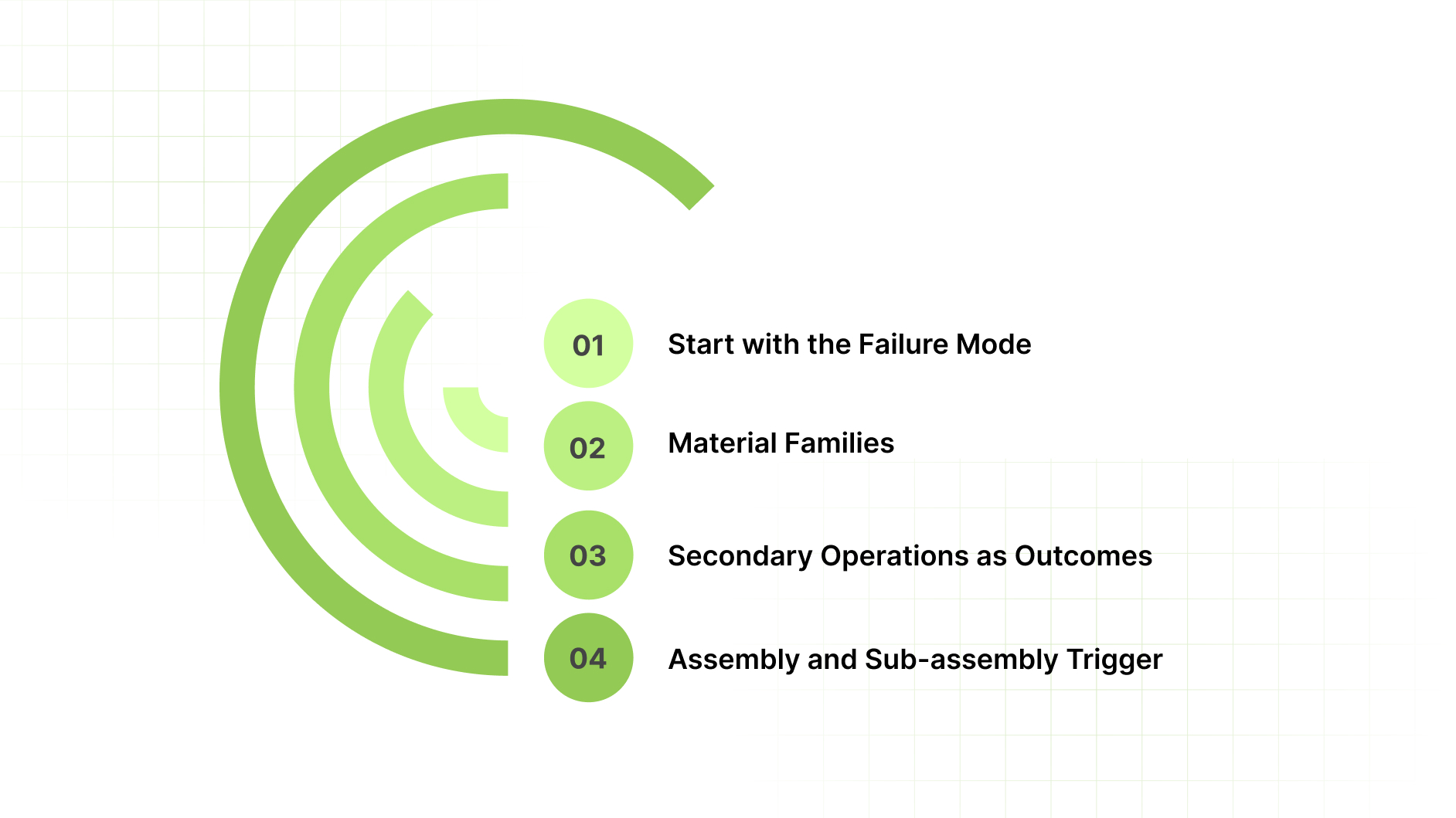
Build the Performance Stack
Material and post-processing choices determine whether performance remains stable across runs and in service. Anchor each selection to the dominant failure mode and the verification step that confirms the outcome. The result is an assembly-ready component with fewer handoffs and fewer opportunities for drift.
Start with the Failure Mode
Before you select a family or a finish, force the program to answer one question: What is the dominant failure risk in service? Most “precision” programs are protecting one of these drivers:
Corrosion risk: Exposure to moisture, salts, cleaners, coolants, or chemical environments.
Wear risk: Sliding contact, particulate exposure, high cycle counts, boundary lubrication.
Strength and fatigue risk: Load transfer, torque, impact, repeated stress cycling.
Magnetic behavior: Requirements driven by sensing, actuation, or avoidance of magnetism.
Conductivity/thermal behavior: Electrical paths, grounding, heat transfer, or conductivity constraints.
This framing keeps the material choice defensible. It also prevents “defaulting to what we always use” when the environment changes.
Select the Material Family
Keep the selection high-level at this stage. You are narrowing down to a family that matches the failure driver:
Iron/iron alloys: Structural components where strength and durability are the priority, and the program needs consistent production behavior.
Bronze: Wear-oriented bushings/bearings where controlled porosity can support lubricity and quiet operation when specified correctly.
Brass: Corrosion- and conductivity-driven parts where the application benefits from the family’s functional behavior and finish expectations.
300 series stainless: Corrosion resistance-first environments where the part must maintain performance despite exposure conditions.
400 series stainless: Strength and magnetic-property-driven applications where those characteristics matter to function and assembly behavior.
Here you are aligning the program to a family that fits the dominant risk.
Specify Secondary Operations as Outcomes
Treat secondary operations as outcome controls. The question here is what outcomes are required for function, stability, and readiness.
Heat treatment: Use when the performance requirement is strength, wear resistance, or stability under load.
Steam oxidizing: Plan when surface behavior and corrosion-related performance need enhancement under real operating exposure.
Copper infiltration/oil or resin impregnation: Plan when porosity behavior is functional, such as wear performance, lubricity, or sealing behavior, rather than accidental.
Sizing/coining: Plan when critical geometry must be stabilized and held consistently at cadence; treat it as part of the control strategy.
Machining/finishing: Use when you have defined which interfaces truly require it; avoid “blanket machining” that defeats net-shape intent.
Coatings/plating / vibratory finishing: Plan when surface condition, corrosion protection, or friction behavior is part of acceptance instead of cosmetic preference.
A useful internal check: if a secondary operation is required for performance, it belongs in the RFQ package as a required outcome and verification expectation.
Evaluate the Assembly and Sub-Assembly Trigger
Assembly support becomes relevant when the pain is operational:
You have labor cost pressure on in-house assembly.
You are managing multiple vendors for one component and losing schedule control.
You run Kanban/JIT and want fewer handoffs and fewer points of failure.
You want parts delivered as functional modules with defined verification gates.
In those cases, assembly readiness is part of “precision,” because it affects yield and line uptime.
A correct stack still fails without tight controls. Supplier selection must focus on how variation is prevented, detected, and contained.
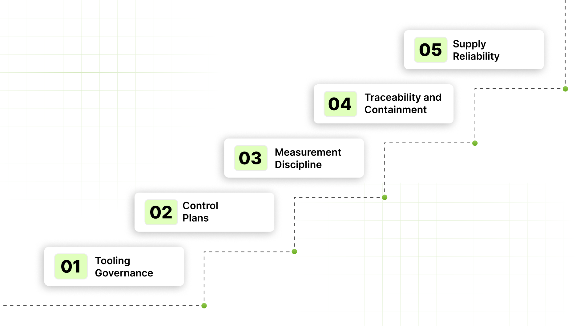
Vet Suppliers by Control Discipline for Precision Components
If you want precision to hold at volume, evaluate suppliers on control discipline, instead of capability claims. Anyone can hit a tight tolerance once; the question is whether they can repeat it for three years without a "hidden" redesign.
Use this audit checklist to force clarity fast:
Tooling Governance
Decision question: Will the supplier reproduce the same part months later without “re-learning” the process?
What to ask for:
Tool ownership and accountability: Who owns, who can modify, who approves changes.
Maintenance records: Documented maintenance schedule, wear tracking, and refurbishment triggers.
Storage and handling: How tooling is protected between runs to stay production-ready.
Change control: A formal approval path for any tooling change that can affect critical features.
What “good” looks like: Clear documentation, named approvals, and a controlled path for any tool intervention.
Control Plans
Decision question: Is there a production playbook that prevents drift and defines what happens when it appears?
What to ask for:
Inspection plan: Which characteristics are checked, with what method, and at what frequency.
Reaction plan: Containment scope, disposition process, and release criteria after a failure.
Critical-feature focus: Confirmation that the plan prioritizes critical-to-function characteristics rather than treating all dimensions equally.
What “good” looks like: Explicit triggers and actions. No vague language. No “we’ll monitor as needed.”
Measurement Discipline
Decision question: Can you trust the measurement system enough to trust the release decision?
What to ask for:
Gage strategy by feature type: Method chosen to match the feature.
Calibration traceability: Calibration status, intervals, and records discipline.
Fixtures and workholding: Stable setups that reduce operator-dependent variation.
Repeatability checks: Evidence that they validate measurement consistency on critical characteristics.
What “good” looks like: Stable measurement, repeatable setups, and clear traceability for gages and fixtures.
Traceability and Containment
Decision question: When a nonconformance happens, how fast can it be isolated without spreading?
What to ask for:
Lot tracking: Ability to isolate product by run/date/status and tie it to inspection results.
Nonconformance isolation: Clear quarantine logic and segregation controls.
Corrective action discipline: Documented cause analysis and a defined verification step before normal release resumes.
What “good” looks like: Rapid isolation, minimal scope creep, and a documented path back to controlled production.
Supply Reliability
Decision question: Can the supplier support your cadence without quality shortcuts?
What to ask for:
Kanban/JIT readiness: Ability to support replenishment flow with predictable lead times.
Packaging and labeling discipline: Consistent identification that protects receiving, inspection, and line-side handling.
Continuity planning: How they manage maintenance, capacity shifts, and disruptions without breaking delivery.
What “good” looks like: Predictable replenishment, disciplined identification, and a continuity plan that protects line uptime.
If your program needs controlled supply and fewer handoffs, you need to qualify a single-source partner. Use the fit check below to see whether Sterling Sintered is the right match.
When to Engage Sterling Sintered for Precision Components at Volume

Sterling Sintered fits programs that need repeatable precision at cadence: volumes from 500 parts/year upward, parts up to 500 grams, and material needs within iron and iron alloys, bronze, brass, or 300/400 series stainless.
They support Kanban/JIT supply models where missed deliveries and variation drift show up immediately on the line.
The role boundary is clear. Sterling does not design parts from scratch. They work from customer-engineered designs and provide powder-metal manufacturability refinements that reduce late tooling churn and prevent hidden secondary work from appearing after award.
If your current workflow involves multiple handoffs, Sterling can bundle tooling, fabrication, secondary outcomes, and assembly/sub-assembly under one accountable process.
Send the print, annual volume, peak cadence, and critical-to-function feature list to request a powder metallurgy manufacturability review.
Conclusion
Precision components fail because “precision” is treated as a label, method selection is made late, and the control plan is implied instead of specified.
Use this framework to maintain stable programs at scale. Define critical-to-function features and how they will be verified. Choose the manufacturing lane using fit filters, then gate powder metallurgy before tooling when it is a candidate.
Build the material and post-processing stack around the real failure mode. Select suppliers based on change discipline, measurement control, and traceability.
If you are re-quoting a high-volume part, seeing drift across runs, or trying to reduce multi-vendor handoffs, run the Sterling Sintered fit check.
That one step prevents preventable tooling churn and keeps precision defensible at production scale.
FAQs
How do you define critical-to-function characteristics for precision components?
Start with the assembly interface. Flag the features that control fit, seal, alignment, and load transfer. Treat everything else as secondary until it can be tied to a functional failure or yield loss.
What quality documents should I request from a precision components supplier?
Ask for an inspection plan and reaction plan for critical features, calibration traceability for the gages used, and lot-level traceability for containment if a nonconformance occurs.
What changes should trigger re-approval for a precision component?
Re-approve any change that can shift critical behavior: material substitutions, tooling modifications, process changes, or measurement method changes on critical characteristics.
How do I reduce variation drift on precision components across production runs?
Focus on controls that survive time: stable measurement methods, defined sampling cadence on critical features, documented containment triggers, and formal tooling change control.
What is the difference between “inspection plan” and “reaction plan” for precision parts?
An inspection plan defines what gets measured, how, and how often. A reaction plan defines what happens when a check fails containment, scope, disposition, and release criteria.